A few weeks ago, I was looking for a summer project and wanted to make something with my msp430. Looking through random parts on SparkFun, I found a megaBrite LED. It’s a programmable LED that is designed for large outdoor displays, so it’s very bright. I ordered one and decided to make a lightsaber that could change color based on user input, or react to the environment with a MQ-3 sensor. This post will outline the construction and design of that project.
Parts (All from SparkFun)
- MegaBrite LED ($9.95)
- MQ-3 Sensor ($4.95)
- Break Away Headers ($1.50)
- 5v Voltage Regulator ($1.25)
- 3.3v Voltage Regulator ($1.95)
- 6 Wire Ribbon Cable ($0.75)
- Rocker Switch ($0.50)
- 6 Pin Header ($0.50)
- 6 Pin Jumper Wire ($1.95)
- Protoboard ($2.95)
- Push Button ($0.50)
- 9v Snap Connecter ($1.25)
Other Parts:
- 20 pin Digital Circuit Tray ($0.50)
- Lightsaber (~$15 ebay)
- msp430 ($10)
Tools Used:
- Exacto Knives
- Drill
- Dremel
- Soldering Iron
So the total project cost isn’t super cheap, and it got more expensive when I connected the LED wrong and burned out the digital circuit that drives it. The megaBrite LED has a 32-bit register that sets the color displayed. It is controlled with a clock pin, data pin, enable pin, and a latch pin. There is a built in voltage regulator, but it only works if the polarity is correct. I also connected the msp430 wrong and burned out a dev kit. If you are careful though, the project is about $50.
This is the design I created:
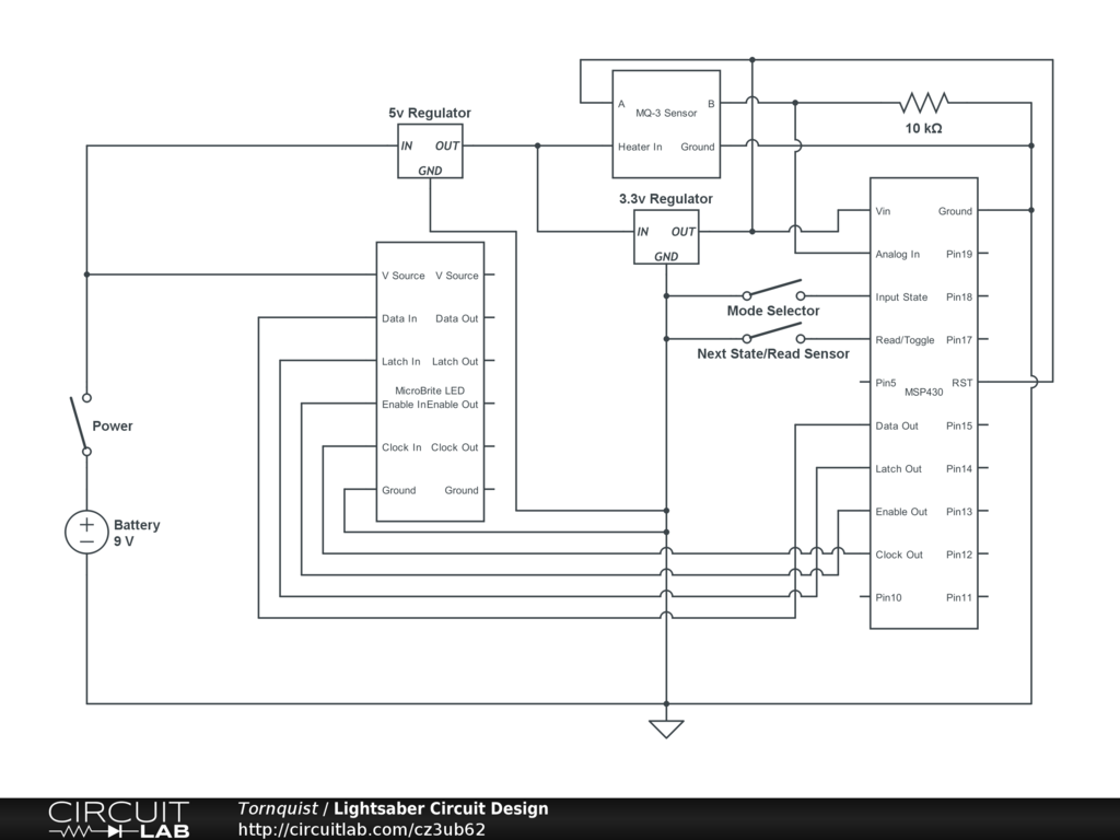
One of the trickiest thing was figuring out the resistor that scales the MQ-3 Sensor. I haven’t actually calibrated the lightsaber fully, so I just just guessed based on the comments found on SparkFun. I tested with 1k and got low values of around 50-70. My diagram says 10k, but I ended up putting a 4.7k resistor in. I might have to switch it out if it does not perform as I’d like, but that really depends on how you are using it programmatically. The smaller the resistor however, the lower the off values is.
The following is the msp430 source code. I use energia, so this logic should function on an arduino as well, you would just need to adjust the final circuit to be based on 5v.
void rgbConversion(
  int red, int green, int blue,
  int clockPin, int latchPin, int dataPin
) {
  digitalWrite(dataPin, LOW);
  digitalWrite(clockPin, HIGH);
  digitalWrite(clockPin, LOW);

  int j = 0;
  int i = 9;
  float color = blue*1023.0/255.0;
  int colorInt = color;
  int temp[] = {0,0,0,0,0,0,0,0,0,0};
  for (j = 0; j < 16; j ++) {
    temp[i] = !!(colorInt & (1 << j));
    if (j < 10) {
      i = i - 1;
    }
  }
  for (i = 0; i < 10; i++) {
    digitalWrite(dataPin, temp[i]);
    digitalWrite(clockPin, HIGH);
    digitalWrite(clockPin, LOW);
  }
  i = 9;
  color = red*1023.0/255.0;
  colorInt = color;
  for (j = 0; j < 16; j ++) {
    temp[i] = !!(colorInt & (1 << j));
    if (j < 10) {
      i = i - 1;
    }
  }
  for (i = 0; i < 10; i++) {
    digitalWrite(dataPin, temp[i]);
    digitalWrite(clockPin, HIGH);
    digitalWrite(clockPin, LOW);
  }
  i = 9;
  color = green*1023.0/255.0;
  colorInt = color;
  for (j = 0; j < 16; j ++) {
    temp[i] = !!(colorInt & (1 << j));
    if (j < 10) {
      i = i - 1;
    }
  }
  for (i = 0; i < 10; i++) {
    digitalWrite(dataPin, temp[i]);
    digitalWrite(clockPin, HIGH);
    digitalWrite(clockPin, LOW);
  }
  digitalWrite(latchPin, HIGH);
  digitalWrite(latchPin, LOW);
}

void reset(int clockPin, int latchPin, int dataPin)
{
  int i = 0;
  digitalWrite(dataPin, LOW);
  for (i = 0; i < 32; i++) {
    digitalWrite(clockPin, HIGH);
    digitalWrite(clockPin, LOW);
  }
  digitalWrite(latchPin, HIGH);
  digitalWrite(latchPin, LOW);
}

//Actual Use
int analogPin = A0;
int buttonPin = 4;
int statePin = 3;
//Control Variables
int state = 0;
int colorValue = 0;
int newState = 0;
//Misc Use Variables (Sequences and counts)
int i = 0;
int j = 0;
//Debounce
int button1Reading = 0;
int lastButton1State = 1; //Start high because button sinks current
long lastDebounce1Time = 0;
long debounceDelay = 50;
int button1Pressed = 1;
int button1Down = 0;
long lastDebounceColorTime = 0;
long debounceColorDelay = 500;
//LED
int clockPin = 9;
int enablePin = 8;
int latchPin = 7;
int dataPin = 6;

void setup() {
  pinMode(buttonPin, INPUT_PULLUP);
  pinMode(statePin, INPUT_PULLUP);
  if (digitalRead(statePin) == HIGH) {
    state = 0;
  } else {
    state = 1;
  }
  pinMode(dataPin, OUTPUT);
  pinMode(clockPin, OUTPUT);
  pinMode(enablePin, OUTPUT);
  pinMode(latchPin, OUTPUT);
  digitalWrite(dataPin, LOW);
  digitalWrite(clockPin, LOW);
  digitalWrite(enablePin, LOW);
  digitalWrite(latchPin, LOW);
  reset(clockPin, latchPin, dataPin);
  rgbConversion(255, 255, 255, clockPin, latchPin, dataPin);
}
int val = 0;
void loop() {
  button1Reading = digitalRead(buttonPin);
  if (button1Reading != lastButton1State) {
    lastDebounce1Time = millis();
  }
  if ((millis() - lastDebounce1Time) > debounceDelay) {
    button1Pressed = button1Reading;
  }
  lastButton1State = button1Reading;
  if (button1Pressed == LOW) { //LOW = Pressed.  Sinks current
    if (button1Down == 0) {
      button1Down = 1;
      if (state == 0) {
        newState = 1;
        colorValue = colorValue + 1;
      }
    }
  } else {
    button1Down = 0;
  }

  ///////////////////////////////////////////////////////////////////////////////////////////////
  ///////////////////////////////////////////////////////////////////////////////////////////////
  ///////////////////////////////////////////////////////////////////////////////////////////////
  ///////////////////////////////////////////////////////////////////////////////////////////////
  ///////////////////////////////////////////////////////////////////////////////////////////////
  ///////////////////////////////////////////////////////////////////////////////////////////////
  ///////////////////////////////////////////////////////////////////////////////////////////////
  ///////////////////////////////////////////////////////////////////////////////////////////////
  //STATE 1 = MQ-3 Input State
  if (state == 1) {
    if (button1Down == 1) {
      val = analogRead(analogPin);
      if (val < 50) {
        colorValue = 0;
      } else if (val < 125) {
        colorValue = 1;
      } else if (val < 250) {
        colorValue = 2;
      } else {
        colorValue = 3;
      }
      //Strange Variable names to reuse those variables written below.
      if (colorValue != i) {
        lastDebounceColorTime = millis();
      }
      i = colorValue;
      if ((millis() - lastDebounceColorTime) > debounceColorDelay) {
        switch(colorValue) {
          case 0:
            rgbConversion(0, 162, 232, clockPin, latchPin, dataPin); //Light Blue
            break;
          case 1:
            rgbConversion(0, 255, 0, clockPin, latchPin, dataPin); //Green
            break;
          case 2:
            rgbConversion(128, 0, 128, clockPin, latchPin, dataPin); //Purple
            break;
          case 3:
            rgbConversion(255, 0, 0, clockPin, latchPin, dataPin); //Red
            break;
        }
        //Force Reset of Timer
        i = i + 50;
      }
    }
  } else {
    ///////////////////////////////////////////////////////////////////////////////////////////////
    ///////////////////////////////////////////////////////////////////////////////////////////////
    ///////////////////////////////////////////////////////////////////////////////////////////////
    ///////////////////////////////////////////////////////////////////////////////////////////////
    ///////////////////////////////////////////////////////////////////////////////////////////////
    ///////////////////////////////////////////////////////////////////////////////////////////////
    ///////////////////////////////////////////////////////////////////////////////////////////////
    ///////////////////////////////////////////////////////////////////////////////////////////////

    if (newState == 1) {

      if (colorValue > 18) {
        colorValue = 0;
      }
      switch(colorValue) {
        case 0:
          rgbConversion(255, 255, 255, clockPin, latchPin, dataPin); //White
          break;
        case 1:
          rgbConversion(255, 0, 0, clockPin, latchPin, dataPin);  //Red
          break;
        case 2:
          rgbConversion(0, 255, 0, clockPin, latchPin, dataPin); //Green
          break;
        case 3:
          rgbConversion(0, 0, 255, clockPin, latchPin, dataPin); //Blue
          break;
        case 4:
          rgbConversion(0, 0, 0, clockPin, latchPin, dataPin); //Off
          break;
        case 5:
          rgbConversion(255, 174, 201, clockPin, latchPin, dataPin); //Rose
          break;
        case 6:
          rgbConversion(255, 255, 0, clockPin, latchPin, dataPin); //Yellow
          break;
        case 7:
          rgbConversion(255, 128, 0, clockPin, latchPin, dataPin); //Orange
          break;
        case 8:
          rgbConversion(200, 191, 231, clockPin, latchPin, dataPin); //Lavendar
          break;
        case 9:
          rgbConversion(163, 73, 164, clockPin, latchPin, dataPin); //Purple
          break;
        case 10:
          rgbConversion(0, 176, 240, clockPin, latchPin, dataPin); //Light Blue
          break;
        case 11:
          rgbConversion(102, 51, 0, clockPin, latchPin, dataPin); //Brown
          break;
        default: //Pulse Options
          i = 255;
          j = 0;
          break;
      }
      newState = 0;
    }
    if (colorValue > 11) {
      if (j == 0)
      {
        i = i - 1;
        if (i < 0) {
          i = 0;
          j = 1;
        }
      } else {
        i = i + 1;
        if (i > 255) {
          i = 255;
          j = 0;
        }
      }
      switch(colorValue) {
        case 12:
          rgbConversion(i, 0, 0, clockPin, latchPin, dataPin); //Red
          break;
        case 13:
          rgbConversion(0, i, 0, clockPin, latchPin, dataPin); //Green
          break;
        case 14:
          rgbConversion(0, 0, i, clockPin, latchPin, dataPin); //Blue
          break;
        case 15:
          rgbConversion(i, i, 0, clockPin, latchPin, dataPin); //Yellow
          break;
        case 16:
          rgbConversion(i, 0, i, clockPin, latchPin, dataPin); //Purple
          break;
        case 17:
          rgbConversion(0, i, i, clockPin, latchPin, dataPin); //Light Blue
          break;
        case 18:
          rgbConversion(i, i, i, clockPin, latchPin, dataPin); //White
          break;
      }
    }
  }
  ///////////////////////////////////////////////////////////////////////////////////////////////
  ///////////////////////////////////////////////////////////////////////////////////////////////
  ///////////////////////////////////////////////////////////////////////////////////////////////
  ///////////////////////////////////////////////////////////////////////////////////////////////
  ///////////////////////////////////////////////////////////////////////////////////////////////
  ///////////////////////////////////////////////////////////////////////////////////////////////
  ///////////////////////////////////////////////////////////////////////////////////////////////
  ///////////////////////////////////////////////////////////////////////////////////////////////
}
To summarize that logic, after I’ve initialized all of the pins I read from the statePin. That’s the button on the side of the lightsaber. Holding that button at startup enables the MQ-3 sensor. With the sensor enabled you can hold another button to read the sensor value and adjust the color accordingly. If the side button is not held at startup, the other button just cycles through lightsaber colors.
And now for the interesting part, photos!
When the lightsaber came, the two main pieces of the handle were screwed together and then both glued into the piece that holds the blade on. To avoid removing the blade, I had to use an exacto knife to cut along the seam which allowed me to remove one side of the lightsaber handle.
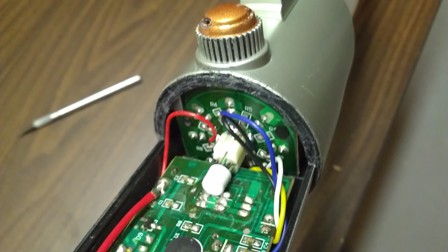
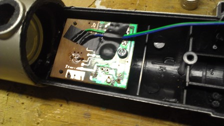
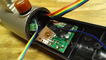
After the seam was cut, and the screws were removed, it was possible to actually open up the lightsaber. This is what it looks like on the inside.
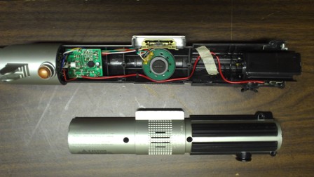
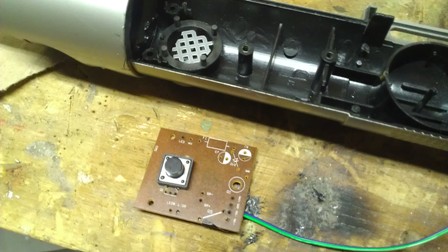
And a photo of how the switch and lighting circuit boards were arranged.
While I was taking apart the lightsaber, I was also working on the individual components that had come from SparkFun, and on writing the drivers to control the LED. This is what the MQ-3 sensor looks like after I’ve soldered on wires. As you can see, some pins are unused. The inside and outside pins on each side are connected, and the middle pins are the heater pins. The diagrams for this device are kind of confusing, but it really is simple to hook up.
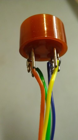
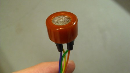
(Orange and Yellow are the heater wires, and blue and green are the sensor wires)
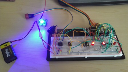
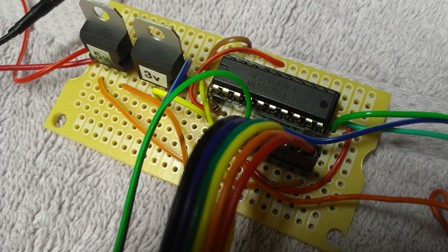
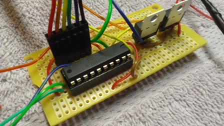
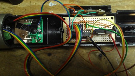
This is a picture of the circuit working on my bread board. After I burned out the first launchpad, I decided to do all of the testing with the micro-controller directly hooked into the circuit. This took longer, but avoided the risk of burning out another dev kit.
With the code written and the individual components soldered, it became time to start assembly of the lightsaber. The first step was getting the button working. I replaced a on/off switch with a momentary push button to control when the sensor would be read, and when to update colors. To keep the spacing constant, I used the same circuit board, I just sanded off the old wiring and drilled holes to solder through. I messed with trying to line the button up just right and was having poor luck with it before my brother suggested I just sand the old wires off.
Moving on, I cut a protoboard to size to fit within the device. And then I began the process of actually attaching my components. It took me most of a day to get everything connected because I wanted to check the outputs from my voltage regulators as I went. With a total project cost of around $60, I really didn’t want to burn out all of my sensors and be forced to either quit or buy it all again.
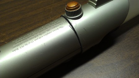
Because I replaced the power button on the old lightsaber design with an input button, I had to add a new power switch.

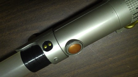
After dremeling out a bunch of light holes and making room for my sensors and other components, this is what the button/LED/sensor region looks like.
I also had to dremel out most of the plastic within the handle. There were plastic regions where the old speaker attached that were sanded. With the interior cleared out, there was room to slide my board in between two screw holes. The board fits tightly and it shouldn’t be a problem with anything moving around.
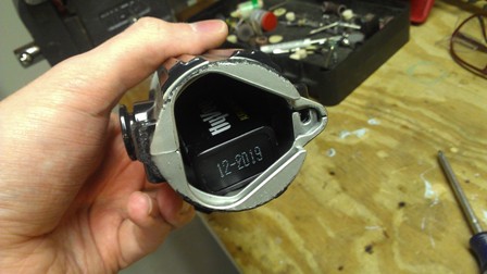
I cleared away space to run the wires, and folded up my longer cables. There wasn’t really a way to show that in a photo as it took two hands to get everything inside and then get the second half of the handle in place. Once the handle was screwed I was able to take more photos. This is what the battery hatch looks like. I have a 9v battery connected with a standard snap harness. The old version had 3 AA batteries, but my design needs too much voltage for that to work. The LED runs at 5.5v to 14v, and the MQ-3 needs 5v for the heater.
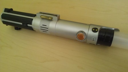
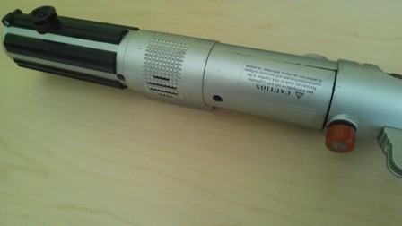
And finally, these are photos of the final project. It looks almost exactly like it did before. I replaced the orange decorative nub thing with an orange sensor, and I added a small switch. Beyond that, you’d have to take the lightsaber apart to see my changes.
And here is a youtube video of the device in operation. You can see me start the device in color-changing mode where the button cycles color, and also in MQ-3 mode. The MQ-3 sensor reads in a value from the environment and then sets the blade color accordingly. You can read more about the sensor on SparkFun if you just google MQ-3. In the video I blow in the sensor to cool it off and make it cycle readings.